What this country needs is some serious competition in the Internet Service Provider market. Really! In most developed countries one can get 10Mbps for about $10/month. Here's what $36/month gets you in Chico California:
And yes, that's actual measured speed, at actual 15-minute intervals, for over three and a half years. Sucks, doesn't it?
Oh, and before I get the inevitable "Wow, you checked internet speed every 15 minutes for three and a half years? Get a life!" comment, I should point out that I wrote a script to collect the data automatically for me and just left it running. (No, I did not click on internetspeedcheck.com 129,254 times!)
This is horrible. This is 1/10 the speed one can get for half this price in South Korea. You can't get internet this slow in France. I suppose I could go to Comcast, but I'd rather give myself an appendectomy with a screwdriver.
February 15, 2015
October 7, 2014
Laser-cut boxes
I frequently build new physics equipment ---as I say, 2nd-best job in the world--- and if the new equipment is something that's going to be used frequently I try to build a semi-permanent version. This frequently requires some sort of electronics box.
Last week we got our new Laser Cutter working here in the College of Natural Sciences, and wow! This changes everything. Previously the process would be "order a metal box of about the right size, then cut holes in about the right places, then print labels with a labelmaker and call it good." With this laser cutter, though, the results can be pretty spectacular.
I took about three hours last weekend designing the box. Most of that time was spent learning how to use the drafting program I installed on my Mac. (DraftSight, if you're curious. Seems good, and free for education use!) I could probably do the same design in about 20 minutes or less now that I know how to use the program. Here's the design:
It's designed to be cut from 1/8" acrylic sheet, and all the tabs interlock so it holds together nicely. The laser cutter software detects different colors and interprets them to mean different laser power/speed. For this one I set the red to high speed and low power, so it just marked the plastic. The black was set to high power, medium speed, so as to cut the pieces.
Here's the resulting box:
That doesn't have the circuitboard in it yet (a student is making it for a project) but it has the mount points for that circuitboard already. It's pretty slick! The acrylic sheet comes in different colors also, so clear is not an absolute necessity. The lettering shows up well: at high speed/low power the laser just makes a fingernail-deep "scratch" on the plastic, which is reasonably visible. To increase the visibility, I rubbed the lettering with a dry-erase marker and then rubbed the surface clean. The marker ink stayed in the lettering groves and shows up quite nicely. I held the pieces together by solvent-welding with Methyl Chloride (use a fume hood!) but superglue or model cement would also work.
I need to re-think how I do this, though. For my entire career, any time I've needed to make holes for banana jacks I just drill a round 5/16" hole; so for this case, I cut a round 5/16" hole. But the banana jacks aren't round! They have flats on two sides so they don't twist in the hole. It's never been an option to use those flats before, since with a drill press all holes are round... But with this laser cutter I can just as easily make holes with those flats on them. Same with the BNC connectors on the front: there's a flat on the threads to keep them aligned. Now I can use that! I can even cut square holes for meters or NASA-style mil-spec switches.
Last week we got our new Laser Cutter working here in the College of Natural Sciences, and wow! This changes everything. Previously the process would be "order a metal box of about the right size, then cut holes in about the right places, then print labels with a labelmaker and call it good." With this laser cutter, though, the results can be pretty spectacular.
I took about three hours last weekend designing the box. Most of that time was spent learning how to use the drafting program I installed on my Mac. (DraftSight, if you're curious. Seems good, and free for education use!) I could probably do the same design in about 20 minutes or less now that I know how to use the program. Here's the design:
It's designed to be cut from 1/8" acrylic sheet, and all the tabs interlock so it holds together nicely. The laser cutter software detects different colors and interprets them to mean different laser power/speed. For this one I set the red to high speed and low power, so it just marked the plastic. The black was set to high power, medium speed, so as to cut the pieces.
Here's the resulting box:
I need to re-think how I do this, though. For my entire career, any time I've needed to make holes for banana jacks I just drill a round 5/16" hole; so for this case, I cut a round 5/16" hole. But the banana jacks aren't round! They have flats on two sides so they don't twist in the hole. It's never been an option to use those flats before, since with a drill press all holes are round... But with this laser cutter I can just as easily make holes with those flats on them. Same with the BNC connectors on the front: there's a flat on the threads to keep them aligned. Now I can use that! I can even cut square holes for meters or NASA-style mil-spec switches.
June 3, 2014
Programmable Servo Controller
This is an update on my earlier Remote key-switch operation post. These things have become rather useful around the lab! In addition to the original key-switch operation, they've been put to use running optical shutters for pump lasers, turning deposition shields inside vacuum chambers, etc. Basically, any time we have a mechanical device we want to be in one of two positions, we use a servo and this board.
The only problem is the inconvenience of programming the limits on the servo. Each application has different desired positions for 'on' and 'off' logic level, and we were having to break out the AVR Programmer each time... So here's the fix. This version has user-programmable limits!
The LEDs indicate power, logic state, and whether the servo is currently 'active'. That last one deserves some more explanation... Servos twitch. They jitter. They are not mechanically (or electrically) quiet. This is an annoyance sometimes, and a serious disadvantage if you need to mount the servo on an optics table. So the other feature to this device is that it turns the servo power off when it's not moving the servo. This may be a disadvantage if you have an application for which the holding force is not negligible, but it's acceptable for our applications. There's a switch in the code so that you can leave the servo power on continuously if you wish.
Another improvement to the previous circuit is that the PWM signal on this version drives a transistor buffer which drives the servo, rather than driving the servo directly with PWM. This allows the circuit to control much larger servos reliably.
It's still limited to 5V supply. The obvious next version would be to add a voltage regulator for the microcontroller, and drive the servo with whatever supply voltage you wanted... but we haven't needed that increase in servo power yet, so haven't bothered.
Here are the EAGLE files and the ATtiny45 code.
The only problem is the inconvenience of programming the limits on the servo. Each application has different desired positions for 'on' and 'off' logic level, and we were having to break out the AVR Programmer each time... So here's the fix. This version has user-programmable limits!
After first turning the device on, apply one logic level (low, say) then press the 'Learn' button. While holding the Learn button, adjust the servo position with the 'Adjust' potentiometer. When the servo is in the desired 'low' position, release the 'Learn' button and the ATtiny45 will store that position in EEPROM. Then apply high logic level, and use the 'Learn' button to teach the microcontroller where the servo should go for high input. Releasing the 'Learn' button stores the high position in EEPROM. From then on, even after power cycling, the device will remember where it needs to go for high and for low input. You can re-program it any time, as often as you like. (Well, up to the limit of EEPROM write cycles for the ATtiny45, which is about 10,000 or so.)
The LEDs indicate power, logic state, and whether the servo is currently 'active'. That last one deserves some more explanation... Servos twitch. They jitter. They are not mechanically (or electrically) quiet. This is an annoyance sometimes, and a serious disadvantage if you need to mount the servo on an optics table. So the other feature to this device is that it turns the servo power off when it's not moving the servo. This may be a disadvantage if you have an application for which the holding force is not negligible, but it's acceptable for our applications. There's a switch in the code so that you can leave the servo power on continuously if you wish.
Another improvement to the previous circuit is that the PWM signal on this version drives a transistor buffer which drives the servo, rather than driving the servo directly with PWM. This allows the circuit to control much larger servos reliably.
It's still limited to 5V supply. The obvious next version would be to add a voltage regulator for the microcontroller, and drive the servo with whatever supply voltage you wanted... but we haven't needed that increase in servo power yet, so haven't bothered.
Here are the EAGLE files and the ATtiny45 code.
September 19, 2013
The "BAD DOG! NO!" alarm
We have a dog. He's a good dog, and very sweet, although a 70-pound golden retriever who thinks he's a lapdog can be a challenge.
One of the current challenges is that he's decided that it's ok to cruise the countertop for goodies while we're off at work and school. We need some negative reinforcement...
Here's just the thing.
If you're curious, the box was made in Google Sketchup and printed in ABS on a Solidoodle. The box holds all the parts and the circuit board, with a 9V battery to run things. I could really get used to this whole 3D printing thing: custom hardware like this is very cool.
One of the current challenges is that he's decided that it's ok to cruise the countertop for goodies while we're off at work and school. We need some negative reinforcement...
Here's just the thing.
The sensor (on the left of the box) is a Passive Infrared (PIR) sensor. I do not know the origin of this particular unit, it's been rattling around my parts-bin for a few years; but similar units are about $10 at Adafruit.com. It puts out a logic high any time it detects motion. That PIR signal is connected to the RESET pin of a 555 timer chip, which is wired to generate a 2.5kHz square wave. The 555 output goes to the piezo buzzer on the right of the box. A switch and power-on LED complete the electronics.
Net result: loud annoying beep any time the sensor detects a dog in the area. We're now working on sensitizing the dog to the noise: every time it goes off we all yell "NO! BAD DOG!" so he starts associating that particular beep with "NO!" Next, we'll put it on the countertop, aligned so that it trips whenever he puts his nose over the edge.
Will it work? I don't know. It'll probably work better than nothing, which is what else we have.
If you're curious, the box was made in Google Sketchup and printed in ABS on a Solidoodle. The box holds all the parts and the circuit board, with a 9V battery to run things. I could really get used to this whole 3D printing thing: custom hardware like this is very cool.
August 30, 2013
Why should the army have all the good drones?
This hack is long overdue. It's been at least two years since I started thinking about how (and whether) to do it, and it's finally coming together. Earlier this month, I finally pulled the trigger on eBay and got a FatShark FPV video system.
The FatShark is a combined video-receiver and video-goggles system. It includes a small video camera and 5.8GHz radio transmitter; the video plays through the goggles. The camera is mounted on a servo-controlled 2-axis gimbal, and a 2-axis gyroscopic/magnetic sensor on the goggles transmits a 433MHz signal to a receiver which controls the gimbal. Net result: A videocamera small enough to mount on an RC plane, that not only shows you the view from the cockpit but tracks your head motion and moves the camera accordingly. Control of the plane is achieved through the regular 2.4GHz RC transmitter/receiver: the FatShark video is a separate system operating on a completely different set of frequencies.

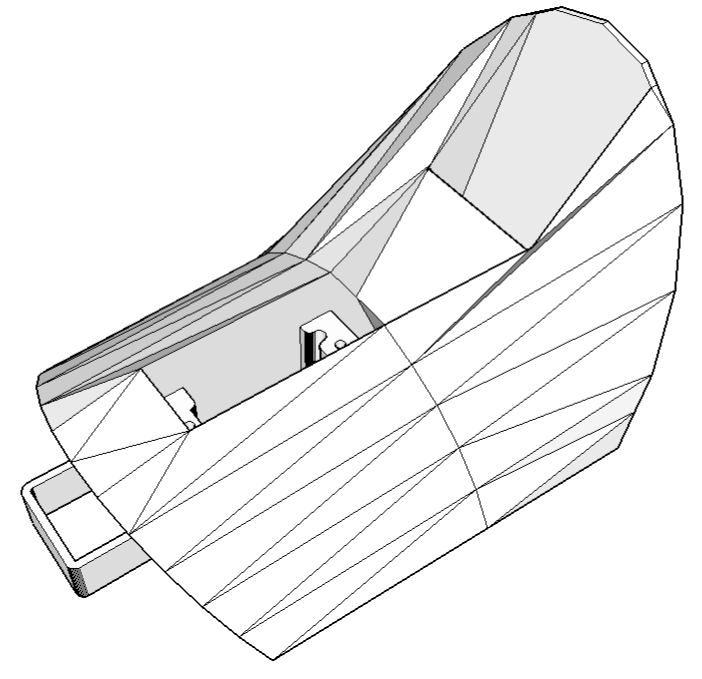
I needed a good way of mounting the camera on the plane. Needed a good plane, too... well, a not-so-good plane, actually; something slow and forgiving and not "special" in any way to either my son or myself. Most of our planes are hand-crafted balsa constructions that take a month to build and involve some emotional cost if they crash, and I figure this thing will crash. We have a "Sky Surfer" that someone gave us, and it fits the bill perfectly: slow, solid foam construction, underpowered (by our standards) and boooring. Someone gave it to us; we use it for teaching other people how to fly RC. It's an absolute pig of a plane, but I think that's probably what we need here. It's also a pusher-prop plane, so there's no obstruction of the front view.The cockpit of the plane is removable, and I now have access to a 3D printer; so I used Google Sketchup to design and print a replacement cockpit that can hold the radio gear. The cockpit just drops in where the stock cockpit came out; no modification to the plane is required. The pan servo on the video gimbal screws into the front slot on the cockpit, with clearance for wiring and for slightly larger servos as well. The angled slot at the back is designed to hold the video transmitter: the antennas are nicely exposed, and there's plenty of airflow onto the transmitter which otherwise gets quite hot. The pan/tilt receiver is stuck to the bottom of the cockpit with doublestick tape.
The original cockpit is held in place by the front tab you can see on the print, and by a magnet that grips a 1-square-cm metal plate on the top-back surface of the cockpit. I designed this replacement cockpit with a recess to mount that plate, but I'm a bit leery of having things come loose in negative-g maneuvers so I strapped the cockpit down with a couple rubber bands just in case.
Now if we just had some good flying weather... Maybe tomorrow! This will be a new experience for me: I've been flying RC planes since high school, but never from "inside the plane!"
Files for this project are available at Thingiverse.
August 4, 2013
3D printing for lab parts...
I reached a fascinating technological milestone this weekend.
I needed some small plastic brackets to hold a sensor for a new experimental apparatus I'm building for the fall semester's Advanced Lab course. So I designed them, in 3D, on my laptop. This took about 30 minutes. When that was done, I went to my lab and printed them, which took another 30 minutes.
Printed. Parts. Real parts. Physical objects. From "Light bulb!" to "Here are the custom parts you just designed" in an hour. SO COOOL!!!
This is a GOOD time to be a nerd.
I needed some small plastic brackets to hold a sensor for a new experimental apparatus I'm building for the fall semester's Advanced Lab course. So I designed them, in 3D, on my laptop. This took about 30 minutes. When that was done, I went to my lab and printed them, which took another 30 minutes.
Printed. Parts. Real parts. Physical objects. From "Light bulb!" to "Here are the custom parts you just designed" in an hour. SO COOOL!!!
This is a GOOD time to be a nerd.
Technical details: parts designed in Google Sketchup, printed in ABS on a Solidoodle 2. This blog post should in no way be construed as an endorsement of Solidoodle, where the company policy appears to be to ship replacement parts on a schedule that would make glaciers wonder about the hold-up, and whose printer is currently printing using a jury-rigged extruder heater element that would make MacGyver shudder.
June 1, 2013
Radioactive isotope decay simulation

My students need to learn LabVIEW —I know, it's proprietary software, and expensive, but until a viable open-source equivalent comes along we're stuck with it— and one of the exercises I have them do is to make a program to analyze radioactive decay. This gives them experience in using counters, plotting data in real time, curve fitting, etc.
The problem arises when I have a dozen students and not so many good sources and detectors. During the students' development of their LabVIEW program, they need multiple re-starts on the measurement. The program NEVER works right the first time, and if you're using neutron-activated indium as a source it's hard to "reset" it when you realize that your block diagram isn't wired right.
I have a dozen Arduinos, though, and I've programmed them to behave as if they were radioactive sources. This way the students can try their program, fix their program, push the reset button on the Arduino and try the program again.
Here's the code. I use pin 13 as an output since the LED allows students to see that it's working, even when their program isn't. The plot shown at the top of this page is actual data from the Arduino, as collected via a student LabVIEW program and plotted in Python. There's a step in the data at about 80 seconds —not sure if that's the Arduino or LabVIEW— but it works well enough for the job.
Once the students are confident that their program works, then I bring out the real sources: neutron-activated indium, neutron-activated silver, and a "cesium-barium cow".
May 12, 2013
"Ayrduino" Single-Sided Arduino Clone
I'm teaching "Electronics for Scientists" this semester, and I wanted to allow each student to have their own Arduino to play with for microcontroller lab exercises and possibly use for their final projects. The Arduino is not very expensive at roughly $30 per, but they add up quickly when you have a whole class of students needing one each. I'd been buying enough electronics equipment over the course of the semester that my department chair was showing an involuntary tic any time I knocked on his office door... So I built my own. They are a stripped-down variant of the Duemilanove.
Hoo-ah:
- Standard Arduino form-factor and mount-points.
- Accepts standard Arduino shields.
- Single-sided board, easy to make with toner-transfer method.
- 16MHz ATmega328.
- No SMT parts.
- On-board 5V regulation.
- Screw-terminal power-in connector, rather than barrel jack.
- Pin-13 LED.
- Lacks on-board USB-Serial conversion, so programming requires an FTDI cable.
- No 3.3V regulator.
- This is as detailed a board as I ever want to make using toner-transfer.
- No TX/RX LEDs.
- No ISP connector.
- Three component-side jumpers. Couldn't quite get all traces on the back side!
My grader, Lena, did most of the drilling and soldering work. She's graduating next week, and I'll miss her, but the graduate program in Nuclear Engineering at University of New Mexico is going to be thrilled.
If you want to make your own single-sided Arduino variant, and this set of pros/cons is acceptable to you, here are the EAGLE files. One of the smart-asses in the electronics class immediately dubbed it the "Ayrduino"...
Note: the Arduino design, on which this is based, is licensed under the Creative Commons Attribution-ShareAlike 2.5 license; so this is available under that same license as well.
Parts list:
- ATmega328P-PU (1)
- 16MHz crystal (1)
- 22 pF cap, ceramic (2)
- Button, momentary tactile switch (1)
- Angled header, 6-pin male (1)
- 0.1µF cap, ceramic (5)
- Red LED (1)
- Green LED (1)
- 1N4001 diode (1)
- 2-position screw terminal (1)
- 7805 regulator (1)
- 10kΩ resistor (1)
- 510Ω resistor (2)
- 47µF Al. Elect. cap (2) (short ones to fit under shield boards)
- Female headers, 8-pin (2) (optional)
- Female headers, 6-pin (2) (optional)
- 28-pin IC socket (1) OR 14-pin IC socket (2) (optional)
- Three short jumper wires
- Single-sided PC board, 0.032" 1/2oz Cu.
April 30, 2013
Minecraft Ore-Block night-light
You can buy a minecraft ore-block night-light... but it's more fun to make your own, and this one is not just redstone. It cycles through the colors of redstone, emerald, lapis lazuli, iron, gold, and diamond. It also pulses slowly; just a subtle fading in and out. My son and my nephew both had birthdays this month; although they're past the age of needing nightlights they're both minecraft nuts so I decided to make these for them.
Let's start with the light. For the light source, I used a 10mm RGB LED from Adafruit. This common-anode RGB LED provides a nice bright color-space, and the diffused package mixes the light well. I first wrote a quick Arduino program to read three potentiometers and adjust the red, green, and blue levels according to those pots. The program would then send the actual RGB values back to the computer via the serial line. This allowed me to experiment with different light mixes in an effort to find the best RGB combination for each color. I could tweak each knob, see the results immediately, and when I found a combination I liked I could check the serial line to see what it was.
Here's the program, and here's what the test-rig looked like:
I eventually decided on these tuples for each type of ore:
Redstone (255,0,0)
Emerald (0,255,0)
Lapis Lazuli (0,0,255) --- those three are easy!
Iron (16,4,0) --- closest I could get to "brown" with the RGB!
Gold (255,115,0) --- maybe a bit less green?
Diamond (0,255,100) --- could've gone more blue, but this works.
These colors are hard-coded into the program, which was downloaded onto the microprocessor before soldering the microprocessor into the board. Here's the program.
Next, the electronics: I chose to use an ATtiny84 microprocessor to drive the light. The ATtiny84 has much more memory than necessary for this purpose, but I needed three separate PWM outputs to do the color mixing (so the ATtiny45 was out) and I didn't have any ATtiny44's handy. The board layout was fairly simple: I used EAGLE CAD, and here's the design:
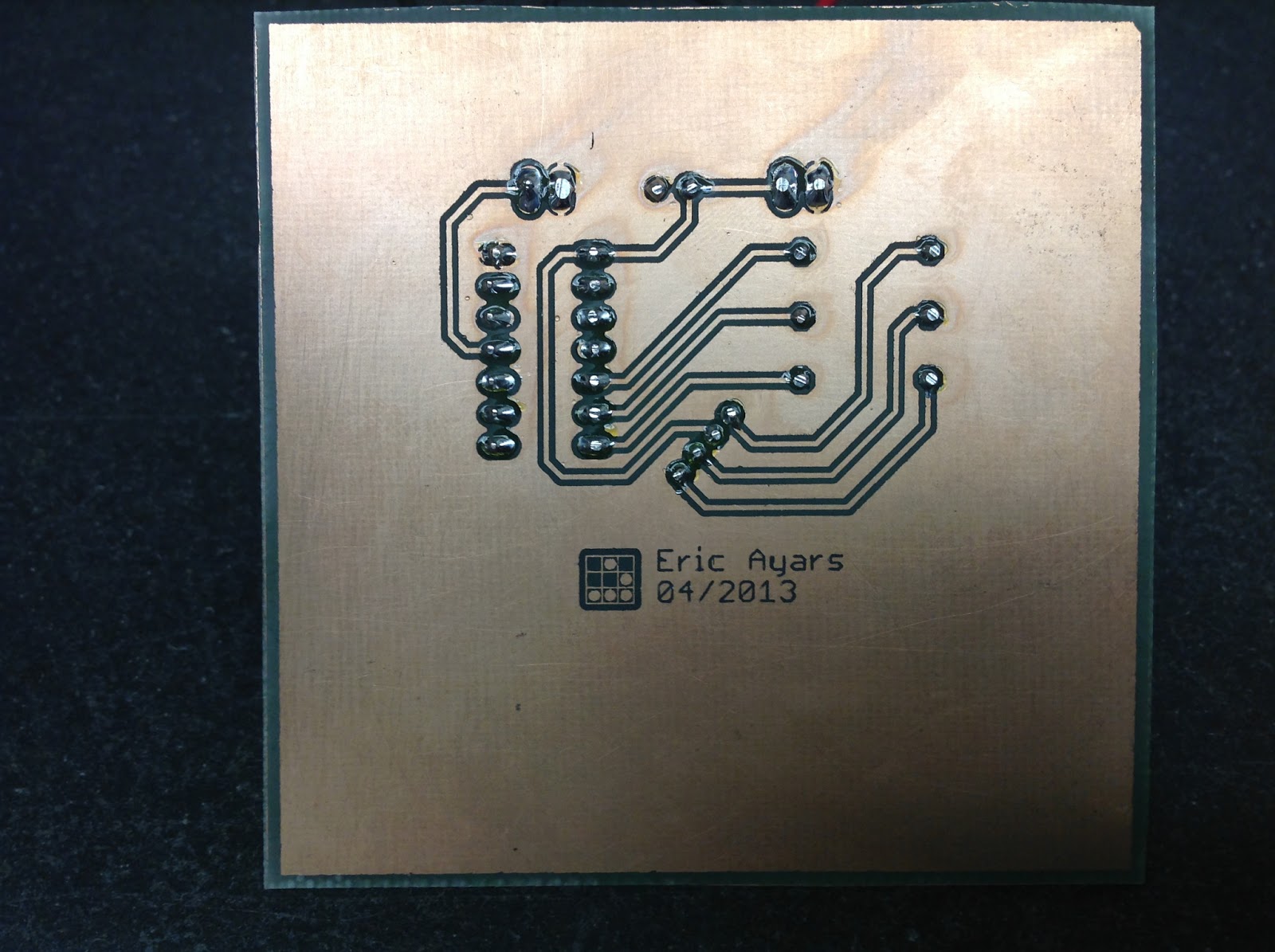
The EAGLE files are available here. I created the board using toner-transfer and FeCl etching.
Next, it was time to make the physical ore-block. I used 1/4" clear acrylic, cut on my table saw. The sides are each 3" high by 2 7/8" wide, and the top is 2 3/4 x2 3/4. I then used a router table to cut a 1/8x1/8" shoulder-groove around each piece.
The side pieces then fit together, each overlapping the next. The top fit perfectly inside the recessed square formed by the sides. The bottom was left open for the moment, but if you're following along on visualizing how this goes together, you'll realize that there is a 2 3/4x2 3/4" recessed square hole there, too --- just the right size for the circuitboard.
Before gluing the pieces together, I sandblasted them ---both sides--- to make them better diffusers.
I then solvent-welded them together using methylene chloride. Plastic model glue would have worked nearly as well, but I work in a building with chemistry labs and fume hoods and solvent-welding acrylic works REALLY well. When finished, I had a nice translucent 3" cube of frosted acrylic, open on the bottom. I also drilled three holes near the bottom of one side of the block; holes that would later accommodate the buttons and power cord.
The outside pattern is key to making this a Minecraft block, of course! I created a single 3x3" side using a vector graphics program, then put five sides together so I could wrap them around the cube. The largest-format laser printer I have available will only print letter-sized paper, so I had to break the wrap into two pieces, like this:
The top piece wraps around three sides of the block, and the bottom folds over the top and fourth side. The extra on the sides wrap around to prevent light leakage around the edges. Here's a link to a .pdf of that design, should you want to make your own block.
To make the "stone" parts of the lamp light-proof I used 3M spray adhesive ("Super 77") to glue a print of this pattern onto a smooth piece of aluminum foil. Next, I carefully cut the pattern out using a sharp new X-Acto blade and a metal straightedge.
I then carefully creased this aluminum-foil/paper label on all fold lines, using the metal straightedge again. I sprayed the aluminum side with adhesive once more, and wrapped the label around the block.
The final assembly step was to provide a power source (salvaged 5V phone charger) and solder the power cord and buttons. I found two buttons that were nearly identical; one was momentary and the other latched. The latched button is used for power, the momentary button cycles through ore-type. The circuitboard fit (with a small amount of sanding) into the recess on the bottom of the cube: I glued it into place with RTV and added four stick-on rubber feet.
It works great, the boys think they are cool, and it's on to the next project: writing a final exam for my electronics course!
April 8, 2013
ISP Clip for ATtiny44/84 (or others!)
I got my start in microcontrollers with the Arduino, as many of us outside of electrical engineering did. (And still do!) The ease of programming that little board makes it a great gateway... and like any gateway, sometimes you go through.
Most of my projects now don't use Arduinos directly. For simple microcontroller applications, it's much more cost-effective to use a bare microcontroller selected for the memory size and pin-count you need to do the job. For me, that usually means either the 8-pin ATtiny45/85 or the 14-pin ATtiny44/84. Both can now be programmed directly using the Arduino IDE with either a commercial programmer or with an Arduino, as described on the excellent MIT High-Low Tech site.
One frustration with these smaller microprocessors, though, is that I either had to take them out of the circuit and wire up a breadboard as shown at MIT's site, or build a 6-pin ISP connector into my project. I built a 6-pin ISP-to-breadboard adapter assembly, which often helped during the prototyping process, but it was not ideal. What I really wanted was something that would clip directly to the chip and let me reprogram it without removing it from the breadboard or circuit.
It turns out the solution had been sitting in my toolbox for the last 15 years, I just didn't know it! Years ago, someone gave me a set of "DIP clips": they're a spring-loaded clip made by 3M that grabs a DIP chip from the top and provides easy contact points to each pin. They're still sold here and elsewhere. I glued a 6-pin ISP header on the side of one of these with wires from the ISP header to the appropriate pins on the clip, and voila! A ISP clip.
This one is for the ATtiny84 (or 44): I just plug my ISP programmer to the clip and put the clip on the ATtiny84: I can then test and debug the microcontroller while it's in the circuit —even if it's soldered into the circuit— without having to build an ISP header in the circuit. There's another 8-pin clip that does the same for me with the ATtiny85 (or 45).
New idea? No... Pretty? No... But it works nicely.
Most of my projects now don't use Arduinos directly. For simple microcontroller applications, it's much more cost-effective to use a bare microcontroller selected for the memory size and pin-count you need to do the job. For me, that usually means either the 8-pin ATtiny45/85 or the 14-pin ATtiny44/84. Both can now be programmed directly using the Arduino IDE with either a commercial programmer or with an Arduino, as described on the excellent MIT High-Low Tech site.
One frustration with these smaller microprocessors, though, is that I either had to take them out of the circuit and wire up a breadboard as shown at MIT's site, or build a 6-pin ISP connector into my project. I built a 6-pin ISP-to-breadboard adapter assembly, which often helped during the prototyping process, but it was not ideal. What I really wanted was something that would clip directly to the chip and let me reprogram it without removing it from the breadboard or circuit.
It turns out the solution had been sitting in my toolbox for the last 15 years, I just didn't know it! Years ago, someone gave me a set of "DIP clips": they're a spring-loaded clip made by 3M that grabs a DIP chip from the top and provides easy contact points to each pin. They're still sold here and elsewhere. I glued a 6-pin ISP header on the side of one of these with wires from the ISP header to the appropriate pins on the clip, and voila! A ISP clip.
This one is for the ATtiny84 (or 44): I just plug my ISP programmer to the clip and put the clip on the ATtiny84: I can then test and debug the microcontroller while it's in the circuit —even if it's soldered into the circuit— without having to build an ISP header in the circuit. There's another 8-pin clip that does the same for me with the ATtiny85 (or 45).
New idea? No... Pretty? No... But it works nicely.
March 10, 2013
Random training interval timer
In addition to various things I'm supposed to do, I race triathlons. One of the training tools we use is the interval workout, in which we alternate high- and low-intensity time intervals during the course of a run or bike workout. There's been a bit of discussion during the Monday-Night run recently about whether it might be advantageous to train with randomized intervals instead of with set intervals.
A typical running interval workout might be a 20min warmup, 5 sets of 1min hard 3min recovery, then 20min cooldown. The idea is to replace the main set with 20 minutes of random intervals, during which the hard and recovery intervals vary randomly in length (within reasonable parameters, of course.)
Typical sports-watches have an interval feature that helps time regular intervals, but they don't do random intervals. Here's my solution: use an ATtiny45 to generate the random intervals, and indicate the intervals via a flashing LED.
And here's the code.
Programming of the ATtiny45 was done via the Arduino IDE: the fuses on the ATtiny45 are set to use the 1MHz internal oscillator. The circuit itself is simply power and ground to the chip (using a 1225 lithium battery) and an LED with current-limiting resistor on PB0 of the microcontroller.
A typical running interval workout might be a 20min warmup, 5 sets of 1min hard 3min recovery, then 20min cooldown. The idea is to replace the main set with 20 minutes of random intervals, during which the hard and recovery intervals vary randomly in length (within reasonable parameters, of course.)
Typical sports-watches have an interval feature that helps time regular intervals, but they don't do random intervals. Here's my solution: use an ATtiny45 to generate the random intervals, and indicate the intervals via a flashing LED.
And here's the code.
Programming of the ATtiny45 was done via the Arduino IDE: the fuses on the ATtiny45 are set to use the 1MHz internal oscillator. The circuit itself is simply power and ground to the chip (using a 1225 lithium battery) and an LED with current-limiting resistor on PB0 of the microcontroller.
June 18, 2012
Quantitative Two-Dimensional Temperature Measurements
Lab Experiments involving the Heat Equation are usually one-dimensional exercises involving a copper pipe and a half-dozen thermocouples. But with DS18B20 "One-Wire" thermometer chips and an Arduino, it's possible to measure hundreds of temperature values simultaneously. Here's what my students Daniel Lund and Lawrence Lechuga and I came up with for 2-D temperature measurements.
We began by laying out a 10x10 grid of sensor locations on a 30cm-square plate of 5mm-thick aluminum. We laid Kapton tape in strips under where the sensor leads would be located, to prevent the leads from shorting against the aluminum plate; then we glued each sensor to the plate using thermal epoxy.
Next, we temporarily attached each sensor to an Arduino microcontroller running FindAddress.ino. This program first determines how many devices are on One-Wire bus; then for each device, it sends the address of that device to the Arduino serial port. A terminal emulator on the attached computer displays those addresses. By running this program with the sensors attached individually, we could then determine the hard-coded addresses of each sensor. One hundred tests later, we had a complete list of sensor addresses, ordered by their physical position on the grid.
Once we knew the individual addresses and corresponding locations of the sensors, we permanently wired all the sensors to the Arduino. Power and ground are provided by the USB connection to the computer, and the data pins for each sensor are all connected via a single wire to one input pin of the Arduino. The data bus is also connected to power via a 1k pull-up resistor. (Note: the datasheet for the DS18B20 calls for a 4.7k pull-up resistor, but we found that with 100 sensors on a single bus a 1k pull-up resistor provided more reliable operation.) The Arduino itself is connected to the computer via a “FTDI Friend” USB-serial converter board.
The completed hardware (bottom side) can be seen below. The plastic stand-offs allow it to be placed flat on a table with the bare top side up.
The final step in construction is to program the Arduino to measure the temperatures and send those temperatures (in order of grid position) to the computer. With this many sensors we found that we were straining the capacity of the microcontroller: although the ATmega328 chip on the Arduino board has 32k of program space, it has only 2k of RAM. This RAM is used by the serial and One-Wire communications libraries as well as by our program, and when the RAM is full the Arduino behaves erratically. Our solution was to store the array of sensor addresses in the 1k array of EEPROM on the microcontroller. This required a second Arduino program (address_storage.ino) which was run once to store the sensor address array in EEPROM. Once that program did its job, we uploaded our final program, ThermoPlate.ino.
The ThermoPlate.ino program operates in two steps after the initialization procedures: first, it sends out a “broadcast” message on the One-Wire bus telling all sensors to record the current temperature. Next, it goes through all the sensor addresses stored in EEPROM. For each address it sends a temperature inquiry to that address, converts the sensor response to °C, and sends the temperature as text down the serial line to the computer. When the Arduino has gotten the temperature from each sensor it sends an EOL character to the serial port, then repeats the process. That’s the final output of the device: line after line of serial data, each line containing 100 temperatures in left-to-right, top-to-bottom order. With our 16-MHz Arduino, it takes just under 2 seconds to measure all points, with the limiting factor being the speed of the One-Wire bus itself.
The computer has to be able to listen to the apparatus and make sense of the incoming data. Since the incoming data is simply text, there is a wide range of possible tools to use for this purpose, ranging from LabVIEW to IDL to C++. For simplicity, we chose to write our program, TempMovie.py, in Python. This program captures each line of data coming in the serial port, splits the line into individual temperatures, rearranges those temperatures into a grid, and then draws a filled contour plot based on that grid data. One can set the temperature scale in the program to cover the expected range of values, and if desired the program will save the raw data for later analysis. The figure below shows a single frame of output of TempMovie.py when a small bag of ice was placed at the upper right and a hot soldering iron was placed near the center.
The image changes as the plate moves towards its new equilibrium state, and one can observe the heat flow in real time. For the sequence of images shown below, the plate was hit with a flame from a propane torch, which was removed after a few seconds. (Time in the video below is sped up by a factor of 4.) Time-dependent thermal data such as this can be compared to numeric solutions of the Heat Equation.
Note: These temperature sensors can detect changes as small as 0.1°C. If you look closely at all of these images, you can see that an area near the lower left corner of the plate is about 0.3°C warmer than the rest of the plate, due to the power dissipation of the microcontroller.
This technique of using multiple DS18B20 sensors controlled by a single Arduino can be used for one-dimensional experiments as well. Twenty-five sensors, evenly spaced along a meter of copper pipe, would make a wonderful replacement for the typical half-dozen thermocouples we’ve all used and hated as undergrads!
The sensors can be ordered from Newark.com or Jameco.com. For our thermal epoxy we used "Arctic Silver Alumina" from Newegg.com.
We began by laying out a 10x10 grid of sensor locations on a 30cm-square plate of 5mm-thick aluminum. We laid Kapton tape in strips under where the sensor leads would be located, to prevent the leads from shorting against the aluminum plate; then we glued each sensor to the plate using thermal epoxy.
Next, we temporarily attached each sensor to an Arduino microcontroller running FindAddress.ino. This program first determines how many devices are on One-Wire bus; then for each device, it sends the address of that device to the Arduino serial port. A terminal emulator on the attached computer displays those addresses. By running this program with the sensors attached individually, we could then determine the hard-coded addresses of each sensor. One hundred tests later, we had a complete list of sensor addresses, ordered by their physical position on the grid.
Once we knew the individual addresses and corresponding locations of the sensors, we permanently wired all the sensors to the Arduino. Power and ground are provided by the USB connection to the computer, and the data pins for each sensor are all connected via a single wire to one input pin of the Arduino. The data bus is also connected to power via a 1k pull-up resistor. (Note: the datasheet for the DS18B20 calls for a 4.7k pull-up resistor, but we found that with 100 sensors on a single bus a 1k pull-up resistor provided more reliable operation.) The Arduino itself is connected to the computer via a “FTDI Friend” USB-serial converter board.
The completed hardware (bottom side) can be seen below. The plastic stand-offs allow it to be placed flat on a table with the bare top side up.
The final step in construction is to program the Arduino to measure the temperatures and send those temperatures (in order of grid position) to the computer. With this many sensors we found that we were straining the capacity of the microcontroller: although the ATmega328 chip on the Arduino board has 32k of program space, it has only 2k of RAM. This RAM is used by the serial and One-Wire communications libraries as well as by our program, and when the RAM is full the Arduino behaves erratically. Our solution was to store the array of sensor addresses in the 1k array of EEPROM on the microcontroller. This required a second Arduino program (address_storage.ino) which was run once to store the sensor address array in EEPROM. Once that program did its job, we uploaded our final program, ThermoPlate.ino.
The ThermoPlate.ino program operates in two steps after the initialization procedures: first, it sends out a “broadcast” message on the One-Wire bus telling all sensors to record the current temperature. Next, it goes through all the sensor addresses stored in EEPROM. For each address it sends a temperature inquiry to that address, converts the sensor response to °C, and sends the temperature as text down the serial line to the computer. When the Arduino has gotten the temperature from each sensor it sends an EOL character to the serial port, then repeats the process. That’s the final output of the device: line after line of serial data, each line containing 100 temperatures in left-to-right, top-to-bottom order. With our 16-MHz Arduino, it takes just under 2 seconds to measure all points, with the limiting factor being the speed of the One-Wire bus itself.
The computer has to be able to listen to the apparatus and make sense of the incoming data. Since the incoming data is simply text, there is a wide range of possible tools to use for this purpose, ranging from LabVIEW to IDL to C++. For simplicity, we chose to write our program, TempMovie.py, in Python. This program captures each line of data coming in the serial port, splits the line into individual temperatures, rearranges those temperatures into a grid, and then draws a filled contour plot based on that grid data. One can set the temperature scale in the program to cover the expected range of values, and if desired the program will save the raw data for later analysis. The figure below shows a single frame of output of TempMovie.py when a small bag of ice was placed at the upper right and a hot soldering iron was placed near the center.
The image changes as the plate moves towards its new equilibrium state, and one can observe the heat flow in real time. For the sequence of images shown below, the plate was hit with a flame from a propane torch, which was removed after a few seconds. (Time in the video below is sped up by a factor of 4.) Time-dependent thermal data such as this can be compared to numeric solutions of the Heat Equation.
This technique of using multiple DS18B20 sensors controlled by a single Arduino can be used for one-dimensional experiments as well. Twenty-five sensors, evenly spaced along a meter of copper pipe, would make a wonderful replacement for the typical half-dozen thermocouples we’ve all used and hated as undergrads!
The sensors can be ordered from Newark.com or Jameco.com. For our thermal epoxy we used "Arctic Silver Alumina" from Newegg.com.
May 16, 2012
Off-topic, but... AT&T sucks.
For the past several years we've gotten our internet through AT&T DSL. Unless you want to support Comcast with your money (and nobody with an interest in net neutrality does) AT&T DSL has been the only option in this town.
I got tired of slow network. Calling AT&T did no good, they claimed things were fine. So I measured the actual speed. Repeatedly!
It just happens that I have access to a pair of very nice servers at my work; I wrote a script on my home machine that downloaded a small file from one of them and recorded the download speed every 15 minutes. An identical script on the second server served as control: should the problem be the server rather than the DSL line, the second server would show it.
After sitting through more than a year of dreadful AT&T service, here are the results.
Notes:
They just switched me to "U-Verse" (still the same "up to 1.5 Mbps" speed) so we'll see if that's any improvement. I'm not holding my breath, and the script is still running.
Oh, and here's the code, which was executed every 15 minutes by cron.
#!/bin/bash
DATESTRING=`date "+%Y-%m-%dT%H:%M:%S%t"`
DOWNLOADSPEED=`curl -s -o /tmp/whatever -w '%{speed_download}' http://REDACTED/randomblock`
echo "$DATESTRING $DOWNLOADSPEED" >> /REDACTED/speedresults.txt
rm /tmp/whatever
I got tired of slow network. Calling AT&T did no good, they claimed things were fine. So I measured the actual speed. Repeatedly!
It just happens that I have access to a pair of very nice servers at my work; I wrote a script on my home machine that downloaded a small file from one of them and recorded the download speed every 15 minutes. An identical script on the second server served as control: should the problem be the server rather than the DSL line, the second server would show it.
After sitting through more than a year of dreadful AT&T service, here are the results.
Notes:
- Up through the end of April of this year, my actual download speed was at most HALF the advertized "up to" speed. For most of last year, I got a quarter of the advertised speed on average.
- The jump in speed at the end corresponds to the date at which many of my neighbors gave up and got Comcast. Speeds after that point are still less than 2/3 the advertised "up to" speed.
- The "control" server (graph not shown here) showed a flat constant speed of nearly 100 Mbps. In other words, the limiting factor was the transfer, not the source.
They just switched me to "U-Verse" (still the same "up to 1.5 Mbps" speed) so we'll see if that's any improvement. I'm not holding my breath, and the script is still running.
Oh, and here's the code, which was executed every 15 minutes by cron.
#!/bin/bash
DATESTRING=`date "+%Y-%m-%dT%H:%M:%S%t"`
DOWNLOADSPEED=`curl -s -o /tmp/whatever -w '%{speed_download}' http://REDACTED/randomblock`
echo "$DATESTRING $DOWNLOADSPEED" >> /REDACTED/speedresults.txt
rm /tmp/whatever
March 21, 2012
Driving multiple Sparkfun 7-segment displays with an Arduino
I'm currently helping a couple of engineering students finish a senior project that didn't get finished last year. Long story... Anyway, it's a bicycle brake tester being built for Paul Components. The mechanical design is great, but they had trouble with the electronics.
Part of those electronics involved writing numbers to a pair of Sparkfun 7-segment displays. There's a lot of discussion on the Sparkfun board about these: apparently they're difficult. I had some issues making them work ---baud rate, for example, which should be set to 9600 in setup() not 2400 as stated in some references--- but it's relatively straightforward once those issues are straightened out. Here's my code, in hopes that it'll be helpful to anyone else trying to write to several 7-segment displays simultaneously.
The serial TX line (second pin given in the SoftwareSerial declaration) should be connected to the RX pin on the corresponding Sparkfun breakout board; the RX line in the SoftwareSerial declaration should be left unconnected. I've only tested it with two boards at a time, but it should work with as many as you have room for on the Arduino. It works fine for just one display, also!
Part of those electronics involved writing numbers to a pair of Sparkfun 7-segment displays. There's a lot of discussion on the Sparkfun board about these: apparently they're difficult. I had some issues making them work ---baud rate, for example, which should be set to 9600 in setup() not 2400 as stated in some references--- but it's relatively straightforward once those issues are straightened out. Here's my code, in hopes that it'll be helpful to anyone else trying to write to several 7-segment displays simultaneously.
The serial TX line (second pin given in the SoftwareSerial declaration) should be connected to the RX pin on the corresponding Sparkfun breakout board; the RX line in the SoftwareSerial declaration should be left unconnected. I've only tested it with two boards at a time, but it should work with as many as you have room for on the Arduino. It works fine for just one display, also!
February 12, 2012
Remote key-switch operation
One of my colleagues, Dr. Shane Mayor, has built a very nice LIDAR system for atmospheric research. It's located at a remote site, at the end of a dirt road, and everything about the system can be controlled remotely except the main pump laser power supply. That supply has a key-switch, which has to be manually turned to activate the system. He asked me to see what I could do to make it all remote-controlled.
Due to the cost of the laser, and Dr. Mayor's unwillingness to void the warranty, my suggestion that he just replace the key-switch with a computer-activated relay was met with some resistance. He absolutely did NOT want me to do anything inside that case! So instead, I built a servomotor key-turner.
The basic idea is to use one of the spare digital lines on his main National Instruments control board to signal the servo controller. When the line goes high, the servo turns the key to the 'on' position, and when the line goes low, the servo turns the key to the 'off' position. Any simple microcontroller should be sufficient for the task: rather than commit an entire Arduino board to the job I just used an Attiny85. Still overkill, but it's so cheap that I don't stock anything cheaper in my parts bin anymore!
Here's the circuit:
And here's the board, which I etched using Pulsar's "Fab-in-a-box" toner-transfer paper.
The software uses Ilya Brutman's Servo8Bit library, and I programmed the Attiny85 using MIT's High-Low Tech instructions. Here's my code. There's a 6-pin ISP header on the board (J1), which I use with an Arduino-as-ISP programmer.
I used the top of a scrapped project box to mount the servo directly above the key and hold the servo output shaft coaxial with the key. The actuator consists of a rubber stopper with a slot cut in it, mounted on a servo control arm. The slot in the stopper fits over the key so that the servo turns the key directly.
It took one re-programming cycle to make the microcontroller turn the servo the right direction (what kind of key turns left for on, anyway?) and then a very simple LabVIEW program to control the digital line to the servo, but that's it! Works great.
Due to the cost of the laser, and Dr. Mayor's unwillingness to void the warranty, my suggestion that he just replace the key-switch with a computer-activated relay was met with some resistance. He absolutely did NOT want me to do anything inside that case! So instead, I built a servomotor key-turner.
The basic idea is to use one of the spare digital lines on his main National Instruments control board to signal the servo controller. When the line goes high, the servo turns the key to the 'on' position, and when the line goes low, the servo turns the key to the 'off' position. Any simple microcontroller should be sufficient for the task: rather than commit an entire Arduino board to the job I just used an Attiny85. Still overkill, but it's so cheap that I don't stock anything cheaper in my parts bin anymore!
Here's the circuit:
And here's the board, which I etched using Pulsar's "Fab-in-a-box" toner-transfer paper.
The software uses Ilya Brutman's Servo8Bit library, and I programmed the Attiny85 using MIT's High-Low Tech instructions. Here's my code. There's a 6-pin ISP header on the board (J1), which I use with an Arduino-as-ISP programmer.
I used the top of a scrapped project box to mount the servo directly above the key and hold the servo output shaft coaxial with the key. The actuator consists of a rubber stopper with a slot cut in it, mounted on a servo control arm. The slot in the stopper fits over the key so that the servo turns the key directly.
It took one re-programming cycle to make the microcontroller turn the servo the right direction (what kind of key turns left for on, anyway?) and then a very simple LabVIEW program to control the digital line to the servo, but that's it! Works great.
December 5, 2011
Christmas-tree water-level alert
Update 12/11/11: A fix to the program--- changed to capSenseRaw() instead of capSense(). The problem with capSense() is that it auto-adjusts the output for touch sensing, rather than absolute capacitive measurement. capSense() reports whatever capacitance it observed the first time as zero from then on. This means that if the water level is high when the Arduino is turned on, high will be interpreted as dry... And it's not very convenient to make sure the sensor is outside the tree-stand whenever you first turn the lights on! Kinda misses the point of this whole exercise if you have to take the sensor out, dry it off, turn the lights on, put it back... But using capSenseRaw() takes care of the problem.
One other note: the sensor has to be very waterproof! The 4 coats of polyurathane were marginal: I've since added a thin coat of silicon RTV and it works much better. If water touches the electrode strips, it shorts out the capacitor and the sensing function returns -2, which leads to erroneous reports of low water level.
-- --- ----- ------- ----------- -------------
About a year ago I made a Christmas-tree water-level sensor that didn't hold up well. Here's a link, but don't make that one. It had a flashing LED, then an audible alarm, to let you know that the water was either low or gone. But why use an LED? As "Joe" suggested in his comment last year, the tree has a lot of lights on it already and why not flash them instead?
Good idea, Joe. Thanks!
The functional problem with last year's model is that the copper traces used for the water-level sensor corroded quickly, and the device was useless in less than a week. The fix I came up with this year is to use a capacitive measurement of water level instead of a conductive measurement. This method (and the necessary CapSense library) is described on the Arduino Playground wiki as an idea for a proximity sensor. Since water has a very high dielectric constant, the presence or absence of water significantly changes the capacitance of a pair of copper traces. Measuring the capacitance of those traces then gives you a measurement of water level while keeping the traces isolated from the water.
Here's my sensor. It's just a strip of strip-type protoboard. (It's 4 traces wide, but I'm only using 2 traces.) It's been covered with 4 coats of spray-on clear polyurethane, so it is (one hopes) completely waterproof. There are two neodymium magnets glued to the back so I can mount it to the inside of the Christmas-tree stand. I forgot to put something in the picture for scale, sorry: it's 9cm long.
With this improved sensor, I can now use the CapSense library to measure water level without worrying about corrosion of the copper traces. And I probably should have stopped there, but Joe's suggestion just seemed to good to pass up. So here's the schematic for the rest of it:
Everything inside the dashed lines is built into a small box. The box has a plug receptacle on the top, into which are plugged the tree's lights. Power to that receptacle is switched by a relay, controlled by an Arduino Pro Mini. (The Pro Mini and relay are powered by a 9V wall-wart transformer, also mounted inside the box.)
If the Arduino detects a "good" water level, it leaves the relay alone and the lights plugged into the receptacle stay on continuously. When the water level drops to "fair", the Arduino cuts the lights briefly once every 5 seconds. When the water level drops below that, the Arduino flashes the lights once a second. Here's the box: I wrapped it in shiny paper to help it "blend in" under the tree.
Here's the code. The values of "fair" and "good" will depend on the exact geometry of your sensor and sensor cable. Uncomment the serial lines in that code and see what values are coming back from the Arduino to determine what levels are appropriate for your setup.
A note for the Arduino-haters: Yes, this could be done with an ATtiny85. Here's why I decided to use a whole Arduino this time:
Update: Since I have the memory available, I tweaked the program a bit. Instead of a fast blink when the tree gets dry, it now blinks "water... water... water..." in Morse code.
One other note: the sensor has to be very waterproof! The 4 coats of polyurathane were marginal: I've since added a thin coat of silicon RTV and it works much better. If water touches the electrode strips, it shorts out the capacitor and the sensing function returns -2, which leads to erroneous reports of low water level.
-- --- ----- ------- ----------- -------------
About a year ago I made a Christmas-tree water-level sensor that didn't hold up well. Here's a link, but don't make that one. It had a flashing LED, then an audible alarm, to let you know that the water was either low or gone. But why use an LED? As "Joe" suggested in his comment last year, the tree has a lot of lights on it already and why not flash them instead?
Good idea, Joe. Thanks!
The functional problem with last year's model is that the copper traces used for the water-level sensor corroded quickly, and the device was useless in less than a week. The fix I came up with this year is to use a capacitive measurement of water level instead of a conductive measurement. This method (and the necessary CapSense library) is described on the Arduino Playground wiki as an idea for a proximity sensor. Since water has a very high dielectric constant, the presence or absence of water significantly changes the capacitance of a pair of copper traces. Measuring the capacitance of those traces then gives you a measurement of water level while keeping the traces isolated from the water.
Here's my sensor. It's just a strip of strip-type protoboard. (It's 4 traces wide, but I'm only using 2 traces.) It's been covered with 4 coats of spray-on clear polyurethane, so it is (one hopes) completely waterproof. There are two neodymium magnets glued to the back so I can mount it to the inside of the Christmas-tree stand. I forgot to put something in the picture for scale, sorry: it's 9cm long.
With this improved sensor, I can now use the CapSense library to measure water level without worrying about corrosion of the copper traces. And I probably should have stopped there, but Joe's suggestion just seemed to good to pass up. So here's the schematic for the rest of it:
Everything inside the dashed lines is built into a small box. The box has a plug receptacle on the top, into which are plugged the tree's lights. Power to that receptacle is switched by a relay, controlled by an Arduino Pro Mini. (The Pro Mini and relay are powered by a 9V wall-wart transformer, also mounted inside the box.)
If the Arduino detects a "good" water level, it leaves the relay alone and the lights plugged into the receptacle stay on continuously. When the water level drops to "fair", the Arduino cuts the lights briefly once every 5 seconds. When the water level drops below that, the Arduino flashes the lights once a second. Here's the box: I wrapped it in shiny paper to help it "blend in" under the tree.
Here's the code. The values of "fair" and "good" will depend on the exact geometry of your sensor and sensor cable. Uncomment the serial lines in that code and see what values are coming back from the Arduino to determine what levels are appropriate for your setup.
A note for the Arduino-haters: Yes, this could be done with an ATtiny85. Here's why I decided to use a whole Arduino this time:
- You need fairly precise timing to measure capacitance repeatably with the CapSense library. That means you need an external crystal rather than the microcontroller's internal oscillator.
- The 12A relay I used needed 9V to activate. (My local Radio Shack didn't have a 5V relay that could switch more than 1A.) An ATtiny needs 5V at most, so I would need a voltage regulation circuit.
- I needed to know the values coming out of the CapSense routines so as to be able to set the cutoffs for "good" and "fair" in the final program. That meant I needed a serial link back to the computer for the setup process.
- Put all this together and hey, it's an Arduino. The Arduino is built already, and I have to write an exam this week also.
Update: Since I have the memory available, I tweaked the program a bit. Instead of a fast blink when the tree gets dry, it now blinks "water... water... water..." in Morse code.
September 14, 2011
Hovercraft
Stefan and I cleaned out the garage last weekend. We found some useful scraps of plywood, and plastic sheeting, and a roll of duct tape, and a leafblower that nobody was using for blowing leaves. Rather than just throw them away, we decided to stick them together first and THEN throw them away. So we built a hovercraft.
This is not the usual electronics-related hack; it has nothing to do with microcontrollers or teaching physics. But it was fun... and it's definitely a hack! Here's how to build your own.
Start with a piece of plywood with an area of 7-9 square feet or so. Circular would probably work best, but anything roughly symmetric should be fine. Cut an off-center hole in it. Cut a piece of plastic sheeting about 6" larger than the plywood.
Now turn it over and cut four (roughly) symmetric holes around an 8-inch circle in the center. We just cut slits a little more than 2 inches wide. We then fed duct tape through the holes so that the center of the plastic was attached to the plywood. Anchor it firmly with more staples, and reinforce the plastic around the holes with —you guessed it— more duct tape.
Air can now blow in the hole in the plywood from the top, inflate the plastic into a flattened donut shape, and exit through the holes in the center. The filled plastic "bubble" makes a skirt for the hovercraft.
Next, turn it right-side up again and attach the leafblower. We used more plastic and duct tape and staples... Lots of staples... More duct tape... and eventually got something that would direct the air through the hole without too much leakage.
Sit on top and turn the blower on — you're good to go!
Obviously a gas-powered leafblower would be an improvement — this one is limited in range by the 50-foot extension cord. It's still fun for sliding around the driveway, though!
This is not the usual electronics-related hack; it has nothing to do with microcontrollers or teaching physics. But it was fun... and it's definitely a hack! Here's how to build your own.
Start with a piece of plywood with an area of 7-9 square feet or so. Circular would probably work best, but anything roughly symmetric should be fine. Cut an off-center hole in it. Cut a piece of plastic sheeting about 6" larger than the plywood.
Put the plastic under the plywood and fold the plastic loosely up over the edges. Tape the plastic down with duct tape. Staple through the tape every 1-2 inches, then put a second strip of tape over the staples to seal it. It should be evenly loose, not tight!
We put the staples too far from the edge in these pictures, and had to put in a second row of staples closer to the edge. More duct tape! Make sure the plastic is completely sealed to the plywood, because when it comes off your hovercraft will stop hovering.Now turn it over and cut four (roughly) symmetric holes around an 8-inch circle in the center. We just cut slits a little more than 2 inches wide. We then fed duct tape through the holes so that the center of the plastic was attached to the plywood. Anchor it firmly with more staples, and reinforce the plastic around the holes with —you guessed it— more duct tape.
Air can now blow in the hole in the plywood from the top, inflate the plastic into a flattened donut shape, and exit through the holes in the center. The filled plastic "bubble" makes a skirt for the hovercraft.
Next, turn it right-side up again and attach the leafblower. We used more plastic and duct tape and staples... Lots of staples... More duct tape... and eventually got something that would direct the air through the hole without too much leakage.
Sit on top and turn the blower on — you're good to go!
Obviously a gas-powered leafblower would be an improvement — this one is limited in range by the 50-foot extension cord. It's still fun for sliding around the driveway, though!
Subscribe to:
Posts (Atom)