February 15, 2015

What this country needs is some serious competition in the Internet Service Provider market. Really! In most developed countries one can get 10Mbps for about $10/month. Here's what $36/month gets you in Chico California:
And yes, that's actual measured speed, at actual 15-minute intervals, for over three and a half years. Sucks, doesn't it?

Oh, and before I get the inevitable "Wow, you checked internet speed every 15 minutes for three and a half years? Get a life!" comment, I should point out that I wrote a script to collect the data automatically for me and just left it running. (No, I did not click on internetspeedcheck.com 129,254 times!)

This is horrible. This is 1/10 the speed one can get for half this price in South Korea. You can't get internet this slow in France. I suppose I could go to Comcast, but I'd rather give myself an appendectomy with a screwdriver.

October 7, 2014

Laser-cut boxes

I frequently build new physics equipment ---as I say, 2nd-best job in the world--- and if the new equipment is something that's going to be used frequently I try to build a semi-permanent version. This frequently requires some sort of electronics box.

Last week we got our new Laser Cutter working here in the College of Natural Sciences, and wow! This changes everything. Previously the process would be "order a metal box of about the right size, then cut holes in about the right places, then print labels with a labelmaker and call it good." With this laser cutter, though, the results can be pretty spectacular.

I took about three hours last weekend designing the box. Most of that time was spent learning how to use the drafting program I installed on my Mac. (DraftSight, if you're curious. Seems good, and free for education use!) I could probably do the same design in about 20 minutes or less now that I know how to use the program. Here's the design:


It's designed to be cut from 1/8" acrylic sheet, and all the tabs interlock so it holds together nicely. The laser cutter software detects different colors and interprets them to mean different laser power/speed. For this one I set the red to high speed and low power, so it just marked the plastic. The black was set to high power, medium speed, so as to cut the pieces.

Here's the resulting box:


That doesn't have the circuitboard in it yet (a student is making it for a project) but it has the mount points for that circuitboard already. It's pretty slick! The acrylic sheet comes in different colors also, so clear is not an absolute necessity. The lettering shows up well: at high speed/low power the laser just makes a fingernail-deep "scratch" on the plastic, which is reasonably visible. To increase the visibility, I rubbed the lettering with a dry-erase marker and then rubbed the surface clean. The marker ink stayed in the lettering groves and shows up quite nicely. I held the pieces together by solvent-welding with Methyl Chloride (use a fume hood!) but superglue or model cement would also work.

I need to re-think how I do this, though. For my entire career, any time I've needed to make holes for banana jacks I just drill a round 5/16" hole; so for this case, I cut a round 5/16" hole. But the banana jacks aren't round! They have flats on two sides so they don't twist in the hole. It's never been an option to use those flats before, since with a drill press all holes are round... But with this laser cutter I can just as easily make holes with those flats on them. Same with the BNC connectors on the front: there's a flat on the threads to keep them aligned. Now I can use that! I can even cut square holes for meters or NASA-style mil-spec switches.

June 3, 2014

Programmable Servo Controller

This is an update on my earlier Remote key-switch operation post. These things have become rather useful around the lab! In addition to the original key-switch operation, they've been put to use running optical shutters for pump lasers, turning deposition shields inside vacuum chambers, etc. Basically, any time we have a mechanical device we want to be in one of two positions, we use a servo and this board.

The only problem is the inconvenience of programming the limits on the servo. Each application has different desired positions for 'on' and 'off' logic level, and we were having to break out the AVR Programmer each time... So here's the fix. This version has user-programmable limits!
After first turning the device on, apply one logic level (low, say) then press the 'Learn' button. While holding the Learn button, adjust the servo position with the 'Adjust' potentiometer. When the servo is in the desired 'low' position, release the 'Learn' button and the ATtiny45 will store that position in EEPROM. Then apply high logic level, and use the 'Learn' button to teach the microcontroller where the servo should go for high input. Releasing the 'Learn' button stores the high position in EEPROM. From then on, even after power cycling, the device will remember where it needs to go for high and for low input. You can re-program it any time, as often as you like. (Well, up to the limit of EEPROM write cycles for the ATtiny45, which is about 10,000 or so.)

The LEDs indicate power, logic state, and whether the servo is currently 'active'. That last one deserves some more explanation... Servos twitch. They jitter. They are not mechanically (or electrically) quiet. This is an annoyance sometimes, and a serious disadvantage if you need to mount the servo on an optics table. So the other feature to this device is that it turns the servo power off when it's not moving the servo. This may be a disadvantage if you have an application for which the holding force is not negligible, but it's acceptable for our applications. There's a switch in the code so that you can leave the servo power on continuously if you wish.

Another improvement to the previous circuit is that the PWM signal on this version drives a transistor buffer which drives the servo, rather than driving the servo directly with PWM. This allows the circuit to control much larger servos reliably.

It's still limited to 5V supply. The obvious next version would be to add a voltage regulator for the microcontroller, and drive the servo with whatever supply voltage you wanted... but we haven't needed that increase in servo power yet, so haven't bothered.

Here are the EAGLE files and the ATtiny45 code.


September 19, 2013

The "BAD DOG! NO!" alarm

We have a dog. He's a good dog, and very sweet, although a 70-pound golden retriever who thinks he's a lapdog can be a challenge.
One of the current challenges is that he's decided that it's ok to cruise the countertop for goodies while we're off at work and school. We need some negative reinforcement...

Here's just the thing.
The sensor (on the left of the box) is a Passive Infrared (PIR) sensor. I do not know the origin of this particular unit, it's been rattling around my parts-bin for a few years; but similar units are about $10 at Adafruit.com. It puts out a logic high any time it detects motion. That PIR signal is connected to the RESET pin of a 555 timer chip, which is wired to generate a 2.5kHz square wave. The 555 output goes to the piezo buzzer on the right of the box. A switch and power-on LED complete the electronics.

Net result: loud annoying beep any time the sensor detects a dog in the area. We're now working on sensitizing the dog to the noise: every time it goes off we all yell "NO! BAD DOG!" so he starts associating that particular beep with "NO!" Next, we'll put it on the countertop, aligned so that it trips whenever he puts his nose over the edge.

Will it work? I don't know. It'll probably work better than nothing, which is what else we have.

If you're curious, the box was made in Google Sketchup and printed in ABS on a Solidoodle. The box holds all the parts and the circuit board, with a 9V battery to run things. I could really get used to this whole 3D printing thing: custom hardware like this is very cool.


August 30, 2013

Why should the army have all the good drones?


This hack is long overdue. It's been at least two years since I started thinking about how (and whether) to do it, and it's finally coming together. Earlier this month, I finally pulled the trigger on eBay and got a FatShark FPV video system.

The FatShark is a combined video-receiver and video-goggles system. It includes a small video camera and 5.8GHz radio transmitter; the video plays through the goggles. The camera is mounted on a servo-controlled 2-axis gimbal, and a 2-axis gyroscopic/magnetic sensor on the goggles transmits a 433MHz signal to a receiver which controls the gimbal. Net result: A videocamera small enough to mount on an RC plane, that not only shows you the view from the cockpit but tracks your head motion and moves the camera accordingly. Control of the plane is achieved through the regular 2.4GHz RC transmitter/receiver: the FatShark video is a separate system operating on a completely different set of frequencies.


I needed a good way of mounting the camera on the plane. Needed a good plane, too... well, a not-so-good plane, actually; something slow and forgiving and not "special" in any way to either my son or myself. Most of our planes are hand-crafted balsa constructions that take a month to build and involve some emotional cost if they crash, and I figure this thing will crash. We have a "Sky Surfer" that someone gave us, and it fits the bill perfectly: slow, solid foam construction, underpowered (by our standards) and boooring. Someone gave it to us; we use it for teaching other people how to fly RC. It's an absolute pig of a plane, but I think that's probably what we need here. It's also a pusher-prop plane, so there's no obstruction of the front view.

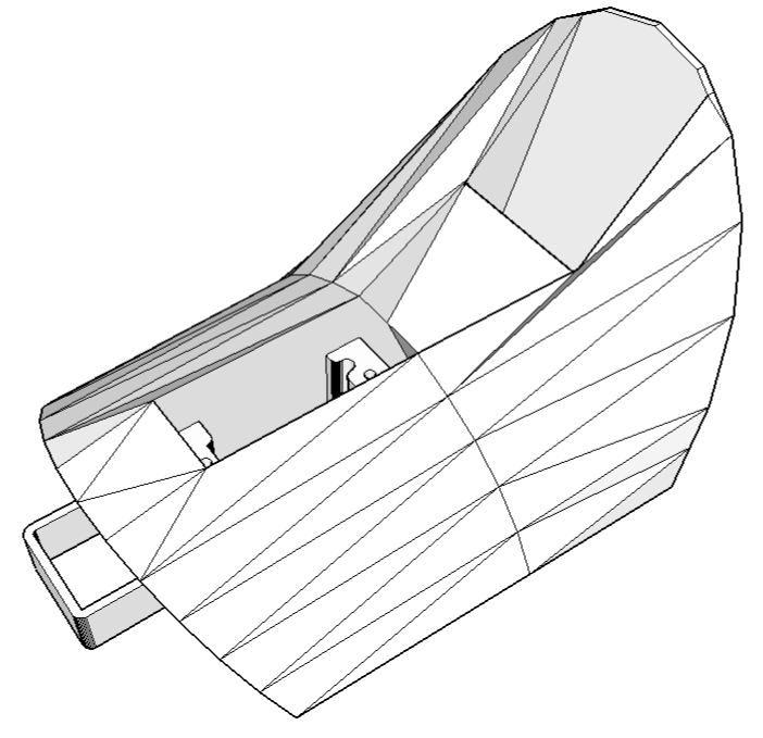
The cockpit of the plane is removable, and I now have access to a 3D printer; so I used Google Sketchup to design and print a replacement cockpit that can hold the radio gear. The cockpit just drops in where the stock cockpit came out; no modification to the plane is required. The pan servo on the video gimbal screws into the front slot on the cockpit, with clearance for wiring and for slightly larger servos as well. The angled slot at the back is designed to hold the video transmitter: the antennas are nicely exposed, and there's plenty of airflow onto the transmitter which otherwise gets quite hot. The pan/tilt receiver is stuck to the bottom of the cockpit with doublestick tape.

The original cockpit is held in place by the front tab you can see on the print, and by a magnet that grips a 1-square-cm metal plate on the top-back surface of the cockpit. I designed this replacement cockpit with a recess to mount that plate, but I'm a bit leery of having things come loose in negative-g maneuvers so I strapped the cockpit down with a couple rubber bands just in case.


Now if we just had some good flying weather... Maybe tomorrow! This will be a new experience for me: I've been flying RC planes since high school, but never from "inside the plane!"

Files for this project are available at Thingiverse.

August 4, 2013

3D printing for lab parts...

I reached a fascinating technological milestone this weekend.

I needed some small plastic brackets to hold a sensor for a new experimental apparatus I'm building for the fall semester's Advanced Lab course. So I designed them, in 3D, on my laptop. This took about 30 minutes. When that was done, I went to my lab and printed them, which took another 30 minutes.

Printed. Parts. Real parts. Physical objects. From "Light bulb!" to "Here are the custom parts you just designed" in an hour. SO COOOL!!!

This is a GOOD time to be a nerd.


Technical details: parts designed in Google Sketchup, printed in ABS on a Solidoodle 2. This blog post should in no way be construed as an endorsement of Solidoodle, where the company policy appears to be to ship replacement parts on a schedule that would make glaciers wonder about the hold-up, and whose printer is currently printing using a jury-rigged extruder heater element that would make MacGyver shudder.

June 1, 2013

Radioactive isotope decay simulation


My students need to learn LabVIEW —I know, it's proprietary software, and expensive, but until a viable open-source equivalent comes along we're stuck with it— and one of the exercises I have them do is to make a program to analyze radioactive decay. This gives them experience in using counters, plotting data in real time, curve fitting, etc.

The problem arises when I have a dozen students and not so many good sources and detectors. During the students' development of their LabVIEW program, they need multiple re-starts on the measurement. The program NEVER works right the first time, and if you're using neutron-activated indium as a source it's hard to "reset" it when you realize that your block diagram isn't wired right.

I have a dozen Arduinos, though, and I've programmed them to behave as if they were radioactive sources. This way the students can try their program, fix their program, push the reset button on the Arduino and try the program again.

Here's the code. I use pin 13 as an output since the LED allows students to see that it's working, even when their program isn't. The plot shown at the top of this page is actual data from the Arduino, as collected via a student LabVIEW program and plotted in Python. There's a step in the data at about 80 seconds —not sure if that's the Arduino or LabVIEW— but it works well enough for the job.

Once the students are confident that their program works, then I bring out the real sources: neutron-activated indium, neutron-activated silver, and a "cesium-barium cow".