
Let's start with the light. For the light source, I used a 10mm RGB LED from Adafruit. This common-anode RGB LED provides a nice bright color-space, and the diffused package mixes the light well. I first wrote a quick Arduino program to read three potentiometers and adjust the red, green, and blue levels according to those pots. The program would then send the actual RGB values back to the computer via the serial line. This allowed me to experiment with different light mixes in an effort to find the best RGB combination for each color. I could tweak each knob, see the results immediately, and when I found a combination I liked I could check the serial line to see what it was.
Here's the program, and here's what the test-rig looked like:

I eventually decided on these tuples for each type of ore:
Redstone (255,0,0)
Emerald (0,255,0)
Lapis Lazuli (0,0,255) --- those three are easy!
Iron (16,4,0) --- closest I could get to "brown" with the RGB!
Gold (255,115,0) --- maybe a bit less green?
Diamond (0,255,100) --- could've gone more blue, but this works.
These colors are hard-coded into the program, which was downloaded onto the microprocessor before soldering the microprocessor into the board. Here's the program.
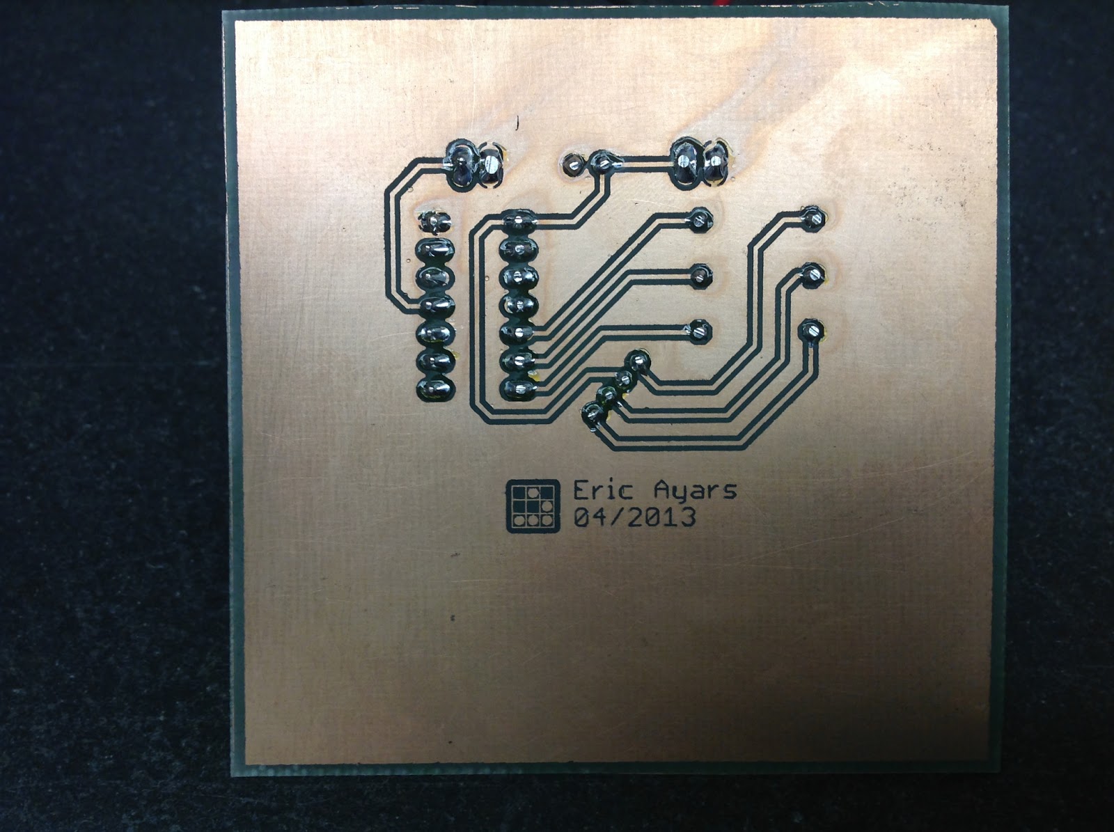
Next, the electronics: I chose to use an ATtiny84 microprocessor to drive the light. The ATtiny84 has much more memory than necessary for this purpose, but I needed three separate PWM outputs to do the color mixing (so the ATtiny45 was out) and I didn't have any ATtiny44's handy. The board layout was fairly simple: I used EAGLE CAD, and here's the design:


The EAGLE files are available here. I created the board using toner-transfer and FeCl etching.

Next, it was time to make the physical ore-block. I used 1/4" clear acrylic, cut on my table saw. The sides are each 3" high by 2 7/8" wide, and the top is 2 3/4 x2 3/4. I then used a router table to cut a 1/8x1/8" shoulder-groove around each piece.
Before gluing the pieces together, I sandblasted them ---both sides--- to make them better diffusers.

The outside pattern is key to making this a Minecraft block, of course! I created a single 3x3" side using a vector graphics program, then put five sides together so I could wrap them around the cube. The largest-format laser printer I have available will only print letter-sized paper, so I had to break the wrap into two pieces, like this:

To make the "stone" parts of the lamp light-proof I used 3M spray adhesive ("Super 77") to glue a print of this pattern onto a smooth piece of aluminum foil. Next, I carefully cut the pattern out using a sharp new X-Acto blade and a metal straightedge.


No comments:
Post a Comment